logo
Send Message
Guangzhou GENY Electric Co., Ltd
english
français
Deutsch
Italiano
Русский
Español
português
Nederlandse
ελληνικά
日本語
한국
العربية
हिन्दी
Türkçe
bahasa indonesia
tiếng Việt
ไทย
বাংলা
فارسی
polski

products details

Created with Pixso. Home Created with Pixso. Products Created with Pixso.
Transformer Test Equipment
Created with Pixso.

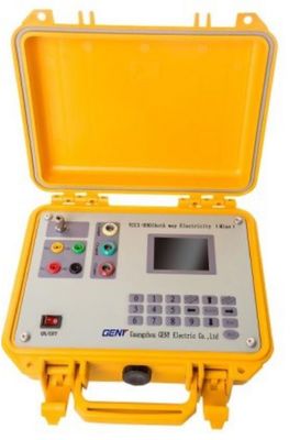
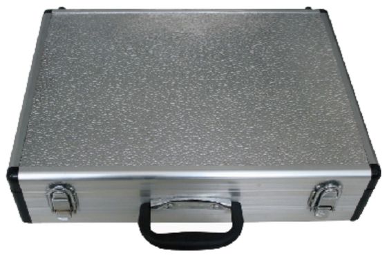
YCCl-9901 Phase And Feeder Identifier For Transformer Test Equipment

YCCl-9901 Phase And Feeder Identifier For Transformer Test Equipment

Brand Name: GENY
Model Number: YCCI-9901
MOQ: 1
Price: negotiate rates
Payment Terms: T/T, L/C, D/P, T/T
Supply Ability: 5 sets / 1 months
Detail Information
Place of Origin:
China
Certification:
ISO, CE
Host Operating Voltage:
AC 3 × 220V
Terminals:
AC220V
Frequency:
50Hz
Terminal Maximum Pulse Current:
10A
Weight:
1700g
Packaging Details:
Plywood cases
Supply Ability:
5 sets / 1 months
Highlight:

YCCl-9901 Feeder Identifier

,

Phase Feeder Identifier

,

Transformer Test Equipment Feeder Identifier

Product Description

YCCl-9901 Phase and Feeder Identifier for Transformer Test Equipment

1.Phase and Feeder Identifier is used to identify users' basic information, such as users' transformer, power and phase line etc, It serves as an effective management approach.

2.The system adopts both pulse method and the powerline carrier signal method to identify users' information. The 2 methods can be used in combination or separately. It offers high testing accuracy, with no misjudgment or unrecognization of users occurring.

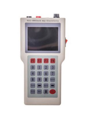
3.The system consists of a host testing device and handheld testing units. The host is installed on the low-voltage side of transformer, and the handheld units are used at the user side for information identification.

Specifications:

YCCl-9901 Phase and Feeder Identifier
Operating Voltage Host AC 3 × 220V
Terminals AC220V
Clamp Current Transformer Range 5A (7mm), 500A (80mm) Flexible Clamp:Optional
Frequency 50Hz
Operating Temperature -10°C ~ +45°C
Host Power Consumption <2W/phase
Terminal Power Consumption <1W (when no pulse sending)
Terminal Maximum Pulse Current 10A
Operating Distance Carrier Communications <2.7km
Pulse >5km


Features & Functions

  • Identification functions for distinguishing the transformers and phases of the measured lines.
  • Identification of the load (the number of energy meters in use) of each phase of the transformers.
  • Display and store the voltage value of the measured lines, and measure the voltage difference between the transformer side and the user side.
  • Display the odd harmonic content (of 3-51st) of the measured line, and store the total harmonics. Display voltage waveform of the measured line.
  • The host device collects pulse signal from the handheld units in the method of voltage pulse detection or by the current clamp to distinguish the phases and the distribution area where the handheld units are located.
  • Identify the branch line, in which the handheld units are located, of distribution area, by using the current clamp to collect the impulse.
  • Using three current clamps, the host displays the voltage, current, angle, active power, reactive power, power factor etc, while no current clamps are used, it display only voltage value with the other parameters shown as zero.
  • 500A and larger clamps or Rogowski coils are available for branch test.
  • Distribution area number can be freely set to distinguish the tested transformers.
  • Distinction of direction and polarity are not required for pulse test, when using handheld unit connection or host's current clamp connection methods.


USAGE METHODS

The host machine

Connect the testing conductor yellow, green, red, and black testing wires with UA, UB, UC, UO terminals in the host machine respectively. The other side is connected to transformer or other power supply device by clamps. (Note: by default, yellow is phase A, green is phase B, red is phase C, and black is UO). Keep safe and follow electricity wiring rules during operation.

Extension

Use the plug side of testing pen to connect extension panel terminal and the clamp side to connect power meter (the red one is phase line and the black one is zero line). Power on after connection.

YCCl-9901 Phase And Feeder Identifier For Transformer Test Equipment 0